


Wszystkie produkty
-
 Bruno NascimentoDziękuję za waszą pomoc i wsparcie w dostarczaniu wysokiej jakości i przystępnych cen produktów.
 -
 Ehsan SalmariSzybka odpowiedź i profesjonalna postawa sprawiają, że nasza współpraca jest płynniejsza!
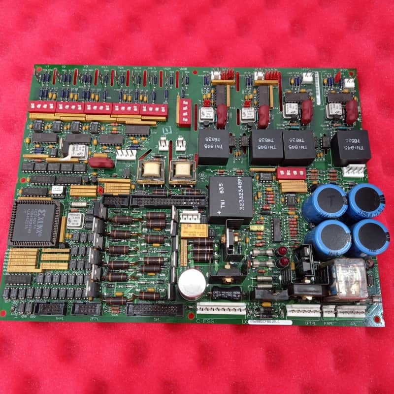
General Electric DS200DCFBG1B DC Zasilacza Sprężyna zwrotna Krytyczna turbina i napęd aplikacji


| Miejsce pochodzenia | USA |
|---|---|
| Nazwa handlowa | GE |
| Orzecznictwo | COO |
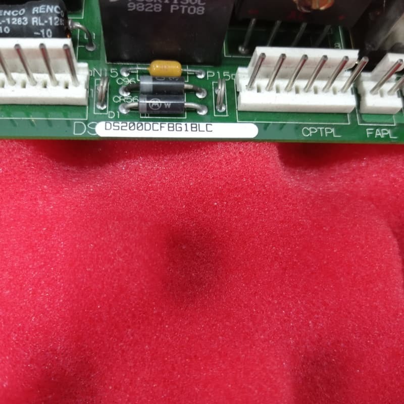
| Numer modelu | DS200DCFBG1B |
| Minimalne zamówienie | 1 |
| Cena | $1800 |
| Czas dostawy | 5-7 dni |
| Zasady płatności | T/t |
| Możliwość Supply | 999 |
Szczegóły Produktu
| Nazwa | General Electric DS200DCFBG1B DC Zasilacza Sprężyna zwrotna Krytyczna turbina i napęd aplikacji | Identyfikator produktu | DS200DCFBG1B |
|---|---|---|---|
| Szereg | Mark v | Gwarancja | 1 rok |
| Głębokość/długość netto produktu | 330 mm | Wysokość netto produktu | 200 mm |
| Waga netto produktu | 2 kg | Szerokość sieci produktu | 100 mm |
| Podkreślić | Płytka sprzężenia zwrotnego zasilacza DC przełącznika DIP SW6,Płytka sprzężenia zwrotnego z 12 zworkami,Płytka zasilacza wejściowego 38 VAC/115 VAC |
||
opis produktu
General Electric DS200DCFBG1B Płyty zwrotnej zasilania prądu stałego Critical Turbine And Drive
Opis produktu:
General ElectricDS200DCFBG1Bjest płytą zwrotną zasilania prądu stałego przeznaczoną do krytycznych zastosowań turbin i napędów, w tym serii EX2000, DC2000 i AC2000. Służy jako centralny węzeł zarządzania energią i monitorowania,przekształcanie mocy wejściowej z transformatora mocy sterowania w różne regulowane napięcia prądu stałego w celu uruchomienia układu napędowego i wentylatorów obudowy.
Kluczowe cechy:
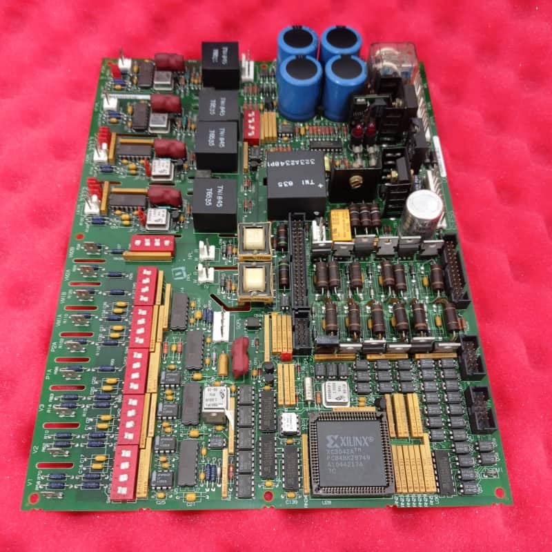
Główną rolą deski jest wytwarzanie i dystrybucja wielu źródeł zasilania na poziomie sterowania, w tym +5V, ±15V i ±24VDC.Zintegrowany z zaawansowanymi obwodami monitorowania, które śledzą podstawowe parametry systemu, takie jak prąd i napięcie armatury., prądu pola silnika oraz wielkości napięcia i sekwencji fazy linii przemiennego prądu.
Cechą charakterystyczną DS200DCFBG1B jest wykorzystanie obwodu VCO (Voltage-Controlled Oscillator).napięcie mostowe wyjściowe, a sygnały miliwoltowe z pola i armatury przerzucają się na sygnały proporcjonalnej częstotliwości (0-500 kHz).Te cyfrowe sygnały częstotliwości są następnie przesyłane do głównego SDCC lub LDCC deski sterującej do przetwarzania, zapewniając wiarygodne informacje zwrotne na temat stanu pracy silnika.
Płyta jest wysoce konfigurowalna za pomocą dwunastu skoków i siedmiu przełączników DIP, umożliwiając opcje specyficzne dla klienta, chociaż są one zazwyczaj ustawione fabrycznie.Zawiera solidne funkcje diagnostyczne i ochronne. Stan napędu +5VDC jest wskazywany przez sygnał /PSEN, który może uruchomić reset mikroprocesora w karcie sterowania, jeśli napięcie nie jest regulowane.płyta jest chroniona bezpiecznikami (FU1, FU2, FU3) dla wyjściowej mocy, z wyraźnymi wskaźnikami wizualnymi ∆LED CR51 i CR55 dla bezpieczników prądu stałego oraz światłem neonowym LT1 dla bezpiecznika prądu przemiennego ∆ do szybkiego rozpoznawania usterek.
![]()
Polecane produkty